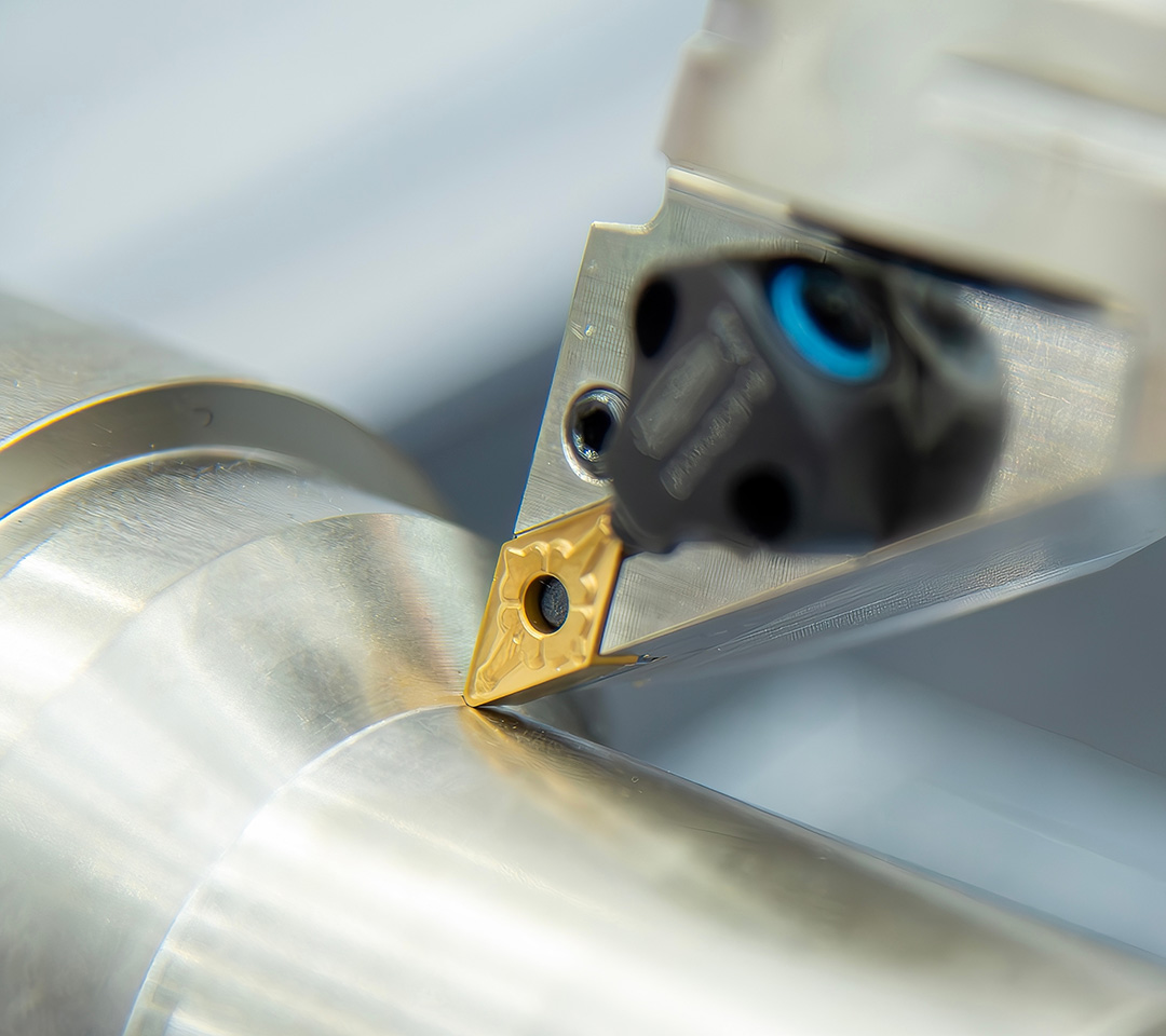

Precision Machining of Aviation Turbine Disks: Systematic Cutting Solutions for Superalloy Components
The aero-engine is known as "the jewel in the crown of modern industry," and the turbine disk is the most critical rotating load-bearing component on that jewel. Directly connected to turbine blades, it operates under a composite regime of temperatures exceeding 1,000°C, high-pressure gas impingement, rotational speeds of tens of thousands of rpm, cyclic alternating stress, and high-frequency vibration. The service life, operational stability, and flight safety limits of the entire engine are determined by the comprehensive performance of the turbine disk.
For this reason, the turbine disk is classified as a Class I critical rotating component of aero-engines—no machining defects, dimensional deviations, or surface damage are permissible.
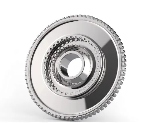
At present, mainstream aviation turbine disk blanks are divided into two categories: powder metallurgy (P/M) superalloys and wrought superalloys. Both materials possess ultra-high room- and high-temperature strength, excellent high-temperature toughness, long-term heat resistance, high-temperature creep resistance, low-cycle fatigue resistance, and hot corrosion resistance, enabling them to meet the thousands of hours of continuous service required by military and civil aviation engines. However, high-performance superalloys inherently present machining pain points: high plasticity, extremely low thermal conductivity, severe work hardening, concentrated cutting heat, rapid tool wear, and susceptibility to residual-stress-induced deformation. Full-process precision machining of turbine disks has become a widely recognized core technical barrier in the manufacturing of aero-power components.
Turbine disks feature complex geometries, including outer-diameter datum surfaces, front and rear end faces, inner-ring bores, deep and shallow annular grooves, radial scallops, end-face mounting holes, and high-precision fir-tree slots. Machining difficulties vary significantly across operations, requiring dedicated cutting tools, high-pressure cooling systems, stepwise stress-relief processes, and micron-level dimensional control systems.
This article breaks down the challenges, process solutions, and practical benefits across four core machining scenarios of turbine disk production.
01 Rough Turning of Outer Diameter and End Faces: How Can Tools Withstand 1,000°C Cutting Heat?
Challenge: Turbine disk blanks have large machining allowances, and a single cut removes a substantial volume of metal. Superalloys have extremely poor thermal conductivity—over 90% of cutting heat accumulates at the tool edge, with instantaneous cutting temperatures exceeding 1,000°C, making inserts highly prone to high-temperature wear, chipping, and plastic deformation. Progressive work hardening accelerates tool consumption; frequent tool changes interrupt production, leading to low efficiency and high per-unit manufacturing costs. Meanwhile, large cutting forces can induce slight vibration of the disk, causing drift in end-face flatness and outer-diameter roundness accuracy.
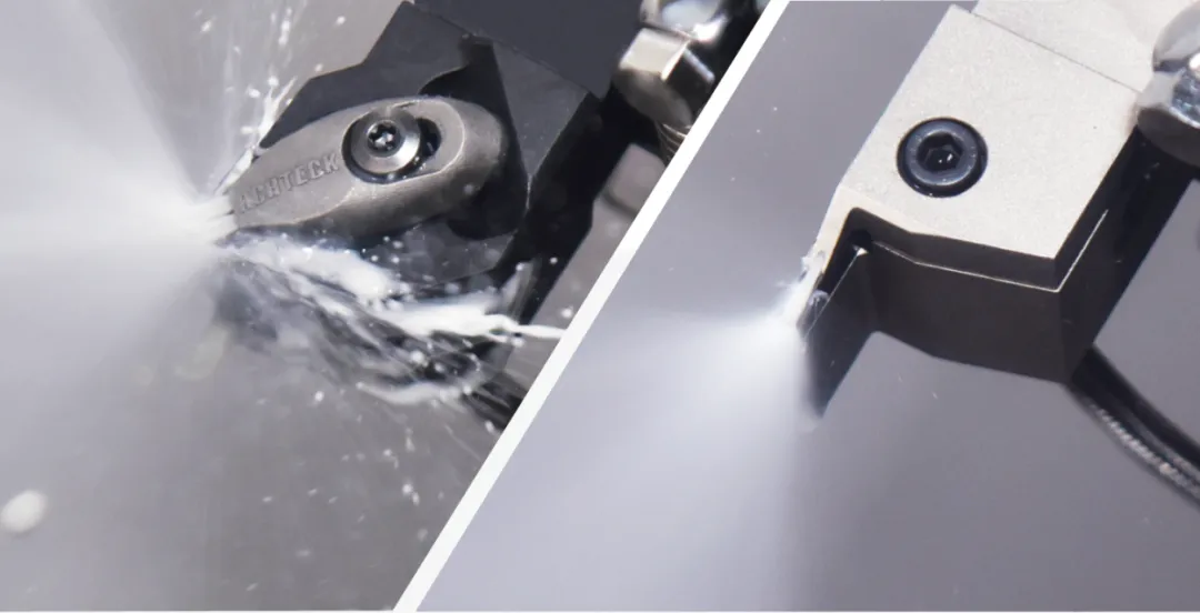
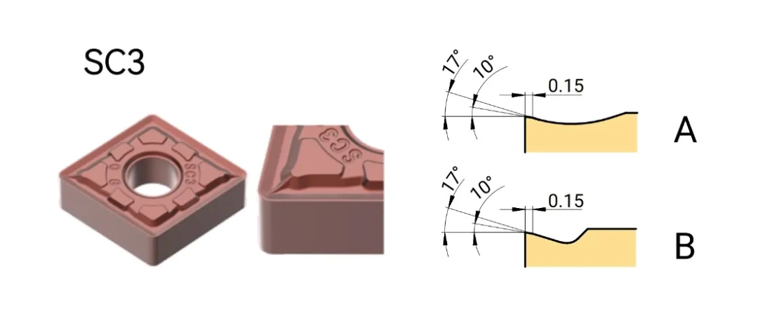
Solution: Use a high-pressure internal-cooling tool holder to deliver cutting fluid directly to the cutting edge, achieving instantaneous forced cooling and flushing away hot chips. Select Achteck AP010S, a dedicated superalloy turning grade, matched with the SC3 large-capacity, low-resistance chipbreaker.
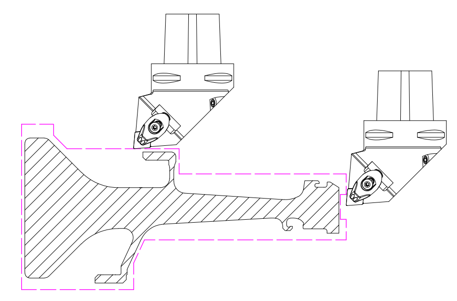
Customer Benefits: Insert wear is uniform and stable with no sudden chipping failures, significantly extending tool life. Reduced cutting resistance lowers machine load, allowing moderate increases in cutting speed and feed rate and shortening per-unit machining time. Comprehensive costs—insert procurement, tool-change downtime, and tool setup—are reduced; in high-volume production, overall machining costs drop significantly, while surface roughness and dimensional consistency improve.
02 Deep Groove Machining: How to Solve Chip Evacuation in Narrow Cavities and Insufficient Tool Overhang Rigidity?
Challenge: Turbine disk seal grooves and weight-reduction grooves are deep with narrow cavities, leaving limited machining space. The high plasticity of superalloys causes chips to curl without breaking easily; iron chips readily accumulate inside narrow grooves, scratching and squeezing the groove bottom and side surfaces. Cutting heat cannot dissipate quickly, and groove-machining tools feature large overhang with weak rigidity, leading to severe edge high-temperature wear and crater wear, and frequent dimensional deviations. Frequent switching between roughing and finishing operations increases auxiliary time through repeated tool setup.
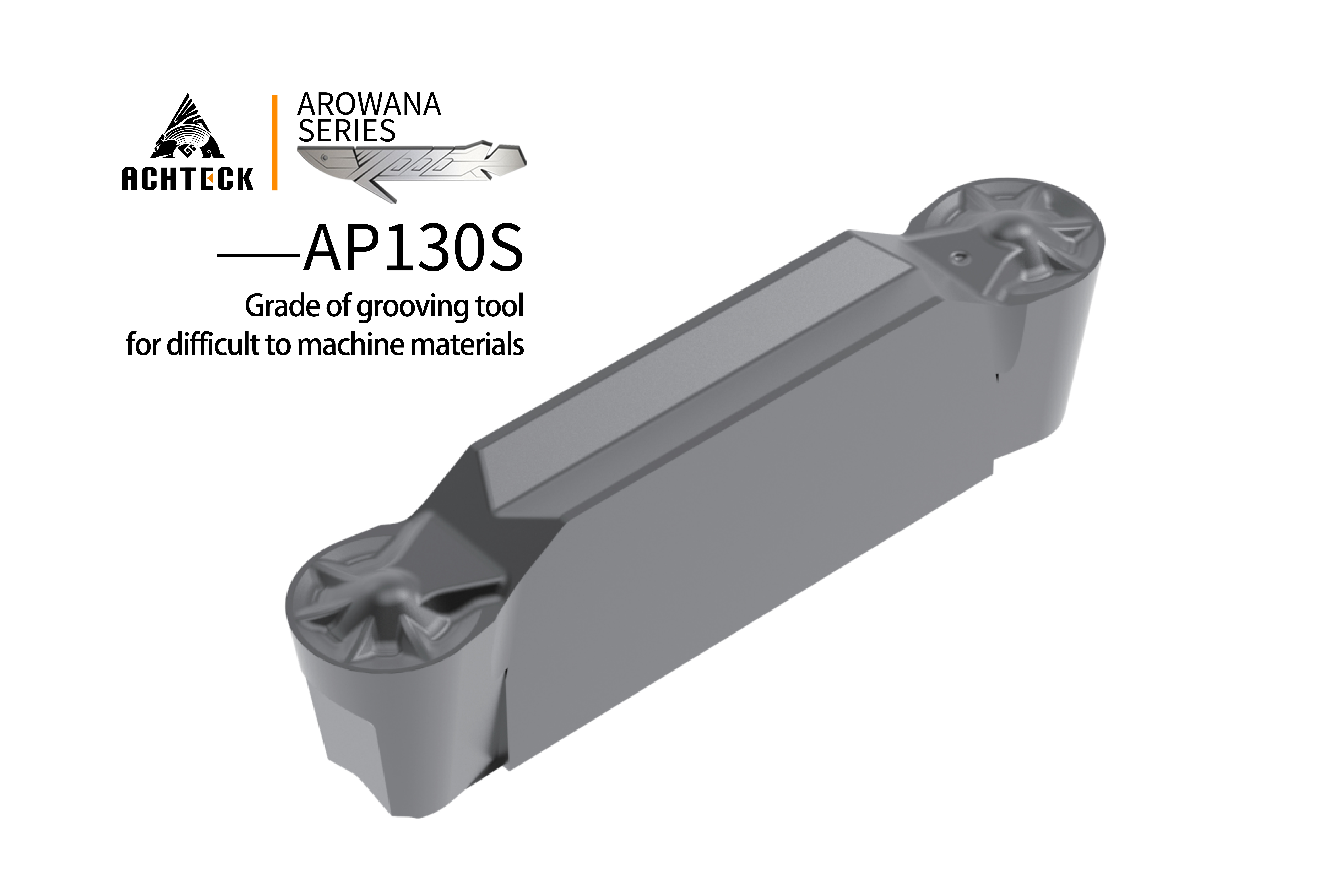
Solution: A high-pressure internal-cooling tool holder is used, delivering high-pressure coolant directly to the cutting zone at the groove bottom to rapidly dissipate accumulated heat and break up and evacuate chips from the groove. The grooving insert features the AP130S high-temperature-resistant dedicated grade, paired with TSR, RS and other dedicated chipbreaker geometries in multiple specifications. AP130S is optimized for substrate toughness under deep-groove interrupted cutting conditions, delivering enhanced impact resistance; the TSR/RS geometries incorporate a staged chip-breaking structure that shears continuous long chips into short chips, thoroughly resolving narrow-groove chip evacuation challenges while reducing chatter marks on groove walls.
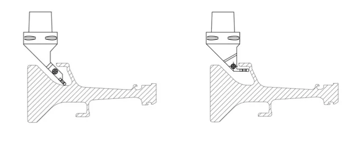
Customer Benefits: Unobstructed chip evacuation eliminates chip-accumulation scratch defects, ensuring surface quality on both groove side walls and the groove bottom. Improved heat and wear resistance of inserts extends single-pass machining time and reduces tool-change frequency. Roughing and finishing can be completed with the same insert series using fine-tuned parameters, simplifying tool inventory and changeover procedures and effectively reducing per-unit tooling costs.
03 Scallop Milling and End-Face Drilling: How to Overcome Thin-Wall Resonance and Chip Winding?
Challenge: Superalloys exhibit extremely high toughness; during milling and drilling, chips wind continuously and are difficult to break. Turbine disk scallops and end-face connecting holes are predominantly thin-walled structures, where cutting forces easily excite workpiece-tool resonance, producing chatter marks and thin-wall deformation. Drill and milling edges sustain continuous high-temperature wear, coatings fail rapidly, and bore diameter drift and scallop profile deviations occur, making batch-to-batch consistency difficult to guarantee.
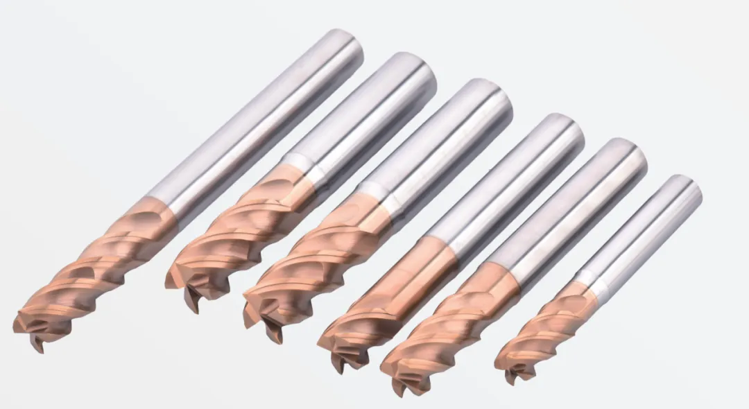
Solution: For milling, use Achteck Pro Series M160 superalloy milling cutters; for drilling, use Achteck D151 high-performance solid drills. The M160 milling cutter adopts an unequal-pitch vibration-damping structure that disrupts resonance frequencies and substantially suppresses thin-wall milling vibration. A multi-layer composite wear- and heat-resistant coating on the tool surface resists high-temperature adhesive wear; edge passivation reduces machining burrs. The D151 drill features an optimized point angle and helical flute geometry, enhancing drill-point impact resistance and chip evacuation, paired with a dedicated high-temperature-resistant coating suited to continuous deep-hole and multi-hole drilling of superalloys.
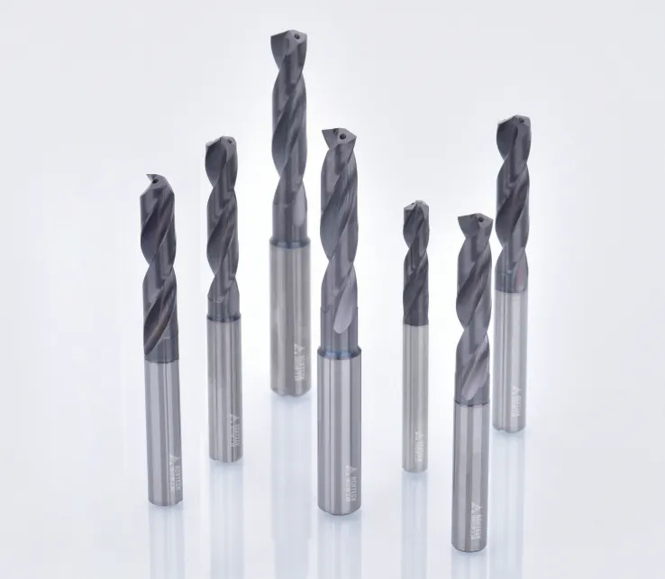
Customer Benefits: The unequal-pitch milling cutter effectively eliminates chatter marks, stabilizes scallop profile dimensions, and keeps thin-wall deformation within process tolerance. The drill's high-temperature-resistant coating extends tool life, eliminating frequent drill changes during continuous multi-hole machining. Hole-wall roughness meets specifications, reducing subsequent reaming and polishing auxiliary operations, improving overall production efficiency and continuously lowering consumable costs.
04 Fir-Tree Slot Forming: How to Control Deformation and Cost for the Highest-Precision Feature on the Disk?
Challenge: The fir-tree slot serves as the assembly datum between the turbine disk and blades, directly determining engine rotor dynamic balance and blade assembly clearance. It is the highest-precision feature on the entire disk, with stringent military-grade standards for dimensional tolerance, profile accuracy, surface roughness, and residual stress. Fir-tree slot machining involves large material removal, and the process releases forging and heat-treatment residual stresses, making disk deformation and slot dimensional drift highly likely. Additionally, the process requires numerous operations and a long cycle; conventional broaching equipment demands high capital investment, resulting in poor cost-effectiveness for new-product small-batch prototyping.
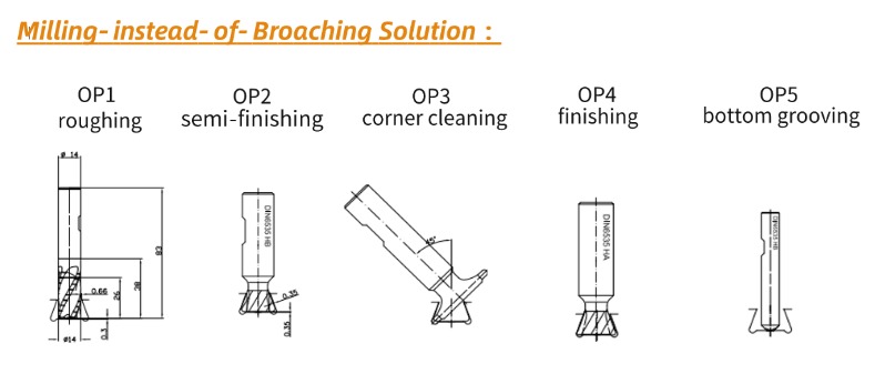
Solution: Adopt a three-stage progressive machining process to gradually release stress and improve accuracy step by step:
① Rough slotting: Remove excess material from the fir-tree slot at large allowance, fully releasing internal residual stress and avoiding subsequent finishing deformation.
② Semi-finish forming and truing: Correct roughing deformation errors, leave uniform and minimal finishing stock, and homogenize machining stress.
③ High-precision milling / form grinding final operation: Select the process route based on production scale. For small-batch new-product prototyping, adopt a "milling-instead-of-broaching" process, using dedicated form milling cutters to complete final precision forming without purchasing expensive dedicated broaches, reducing R&D investment. For high-volume mass production, form broaching offers higher process stability and better machining consistency, suited to sustained batch production.
Customer Benefits: The stepwise stress-relief process effectively controls fir-tree slot machining deformation, keeping micron-level dimensional accuracy stable and controllable. Matching milling and broaching routes by scenario balances the economics of new-product development with the stability of mass production. Slot surfaces are free of machining damage and residual stress is controlled, meeting aviation-component inspection and fatigue-life quality standards and reducing product rejection rates.
Precision machining of aviation turbine disks is a comprehensive manufacturing engineering endeavor that deeply integrates precision mechanical cutting processes, specialty tool material technologies, high-temperature cooling systems, heat-treatment stress relief, and full-process micron-level quality control.
The inherent machinability difficulties of turbine-disk superalloy substrates mean that no single tool or single process can resolve the full spectrum of pain points—deformation, tool wear, and accuracy drift. A systematic, turnkey machining solution must be established: by matching dedicated tool grades and chipbreakers per operation, enforcing high-pressure internal cooling for temperature control, applying stepwise stress-relief processes, and adopting vibration-damping tool structures, the five core challenges of superalloy cutting—high cutting temperature, work hardening, difficult chip evacuation, thin-wall vibration, and residual-stress deformation—can be systematically overcome.
Achteck's full range of difficult-to-machine material cutting tools forms a complete supporting system: AP010S / AP100S / AP130S turning inserts cover all turning and grooving scenarios for turbine disks; M160 / M170 series dedicated milling cutters and D105 / D151 series carbide drills accommodate scallop milling and end-face drilling operations. The entire tool series is purpose-developed for aviation superalloy conditions, balancing machining efficiency, tool life, machining accuracy, and production cost. It supports stable production of aero-engine turbine disks across the full lifecycle—from new-product prototyping to mass production—providing turnkey precision cutting solutions for the domestic localization of aerospace power core components and the high-quality development of high-end equipment manufacturing.