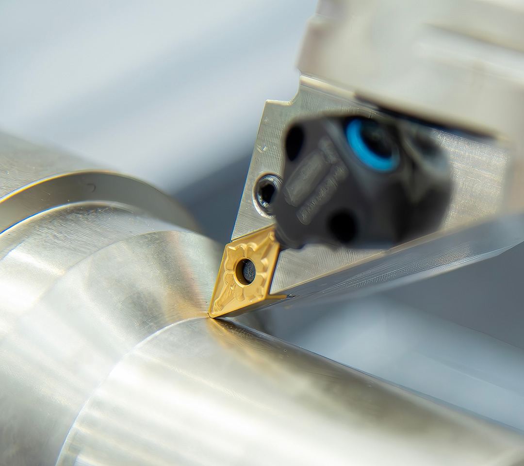
OD Grooving: Three Pain Points, Dialed In in One Setup — Sidewall Scratches, Insert Chipping, Dimensional Drift
Outer diameter grooving is one of the most frequently performed operations in CNC turning, and it has long been a common pain point for process engineers and machine setters on the shop floor.
Chip evacuation, cutting loads, and the rigidity of the tooling–workpiece–tool system are deeply coupled. A slight deviation during machining can easily trigger typical quality issues: in minor cases, groove sidewalls left with chip marks and inconsistent groove width; in serious cases, insert tip chipping and entire batches of scrapped parts. The impact goes far beyond the surface — it lowers yield, drives up non-wear insert costs, and consumes enormous setup time on repeated root-cause troubleshooting and trial cuts, dragging down the entire line's production rhythm.
Drawing on extensive frontline process service experience from Achteck Tools' engineering team, we systematically break down the three most common failure modes in OD grooving — explaining the root mechanisms and providing actionable on-site adjustment guidance to help you avoid unnecessary detours.
This reflects Achteck Tools' core service philosophy: we deliver far more than a single insert. We provide a complete grooving solution covering insert geometry selection, cutting path optimization, and system rigidity compensation — helping you achieve stable, efficient, and cost-effective grooving operations on the shop floor.
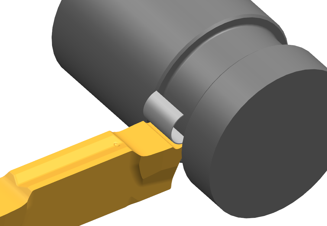
Failure Mechanism: Chip curling width directly determines sidewall surface quality
When the chip curling width ≥ groove width, the chip is squeezed and trapped inside the groove cavity, rubbing and scraping against the sidewall and forming scratch defects.
When the chip curling width < groove width, the chip can evacuate smoothly, avoiding sidewall interference and damage.
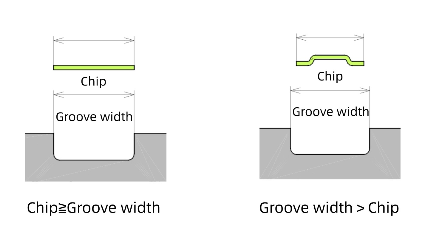
Match the operating condition and select ground-type or pressed-type chipbreaker inserts. The chipbreaker geometry constrains the chip curling range so that the chip curls narrower than the groove width — eliminating sidewall chip scratching at the evacuation source. Cleaner groove sidewalls, smoother chip flow, and less downtime for chip clearing and rework.
Failure Mechanism: When groove-bottom corner radius is machined directly via circular interpolation, the insert simultaneously withstands radial and axial cutting forces. The combined load on the cutting edge is excessive, easily leading to tip chipping.
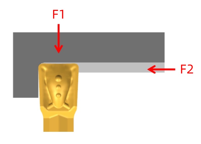
Step-by-Step Cutting Path Decomposition
Step1: Radial feed to the groove bottom depth.
Step2: Retract in X, leaving a radius machining allowance.
Step3: Feed in Z to remove the sidewall allowance.
Step4:Finally execute the circular contour interpolation.
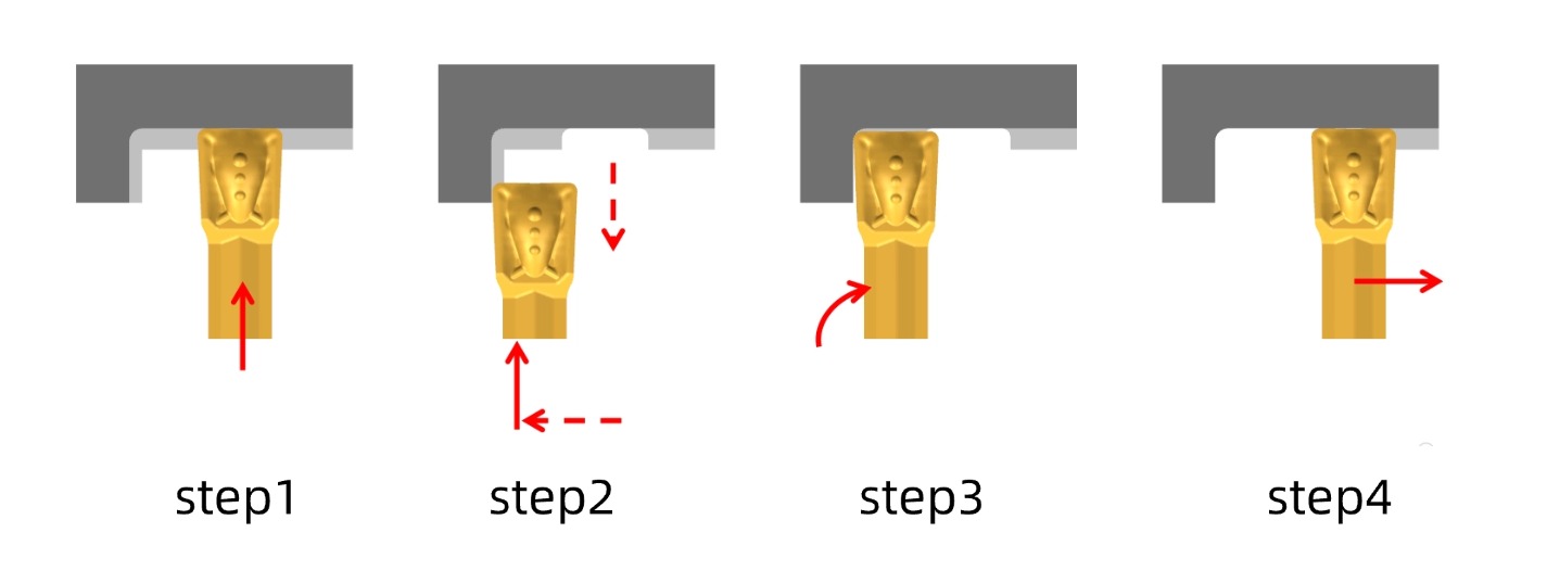
By splitting the bi-directional combined cut into unidirectional cutting actions, edge loads are distributed and tip fracture risk is reduced.
Achteck Tools' engineering team can work with you — based on insert geometry, grade, and cutting path — to break down "radius interpolation" into safer cutting motions, delivering more stable insert life and more reliable groove-bottom contours.
Dimension Deviation in Low-Rigidity Workpieces (The "Double-Diameter" Phenomenon)
Failure Mechanism: When workpiece–tool system rigidity is insufficient, as grooving transitions from radial plunge to Z-direction traverse finishing, the toolholder deflects elastically, causing the insert to penetrate and overcut. The same groove ends up with two different diameters — resulting in dimensional out-of-tolerance.
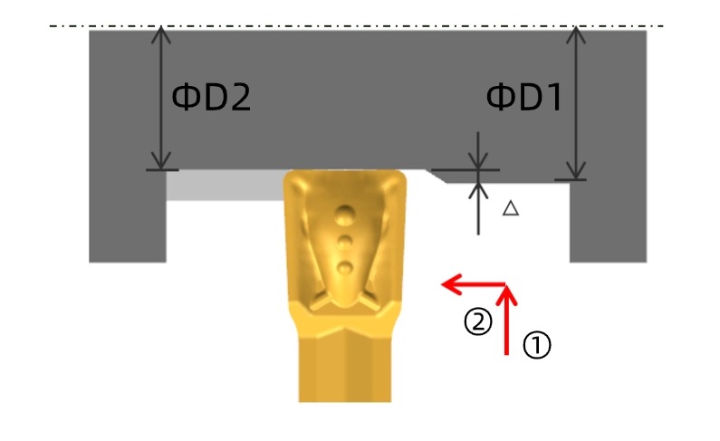
Offset Compensation
Step 1: Groove radially to the target groove-bottom diameter.
Step 2: Retract in X by the compensation offset (Δ/2) to counteract the toolholder elastic deflection.
Step 3: Execute the traverse finishing pass to eliminate overcut and ensure groove-bottom diameter consistency.
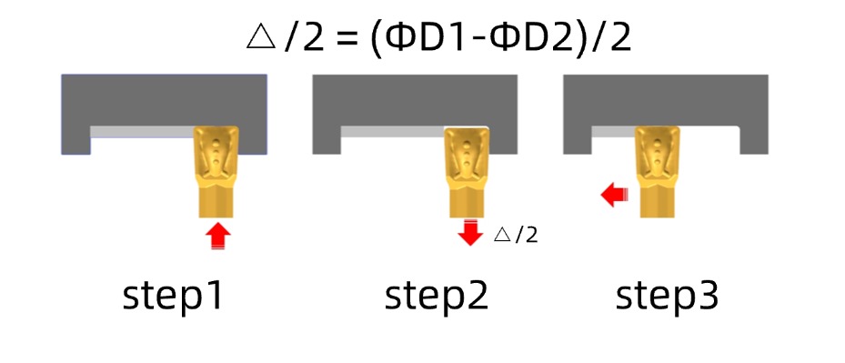
For slender shafts, thin-walled sleeves, and other low-rigidity workpieces, Achteck Tools provides not only groove tool systems and insert selection but also on-site rigidity assessment and compensation parameter recommendations — reducing the "double-diameter" defect and delivering more consistent groove-bottom dimensions.
Sidewall scratches, tip chipping, and dimensional drift in OD grooving are often not simply a tool quality problem — they result from a mismatch among chip form, cutting path, and system rigidity. Master the process logic, select the right insert, and optimize the program, and you can effectively lower grooving defect rates, reduce abnormal tooling consumption, and safeguard both part quality and production stability.
If you are currently facing OD grooving challenges on the shop floor —
Sidewall scratches, tip chipping, dimensional drift, poor chip evacuation, short tool life…
Contact Achteck Tools for customized on-site process support.