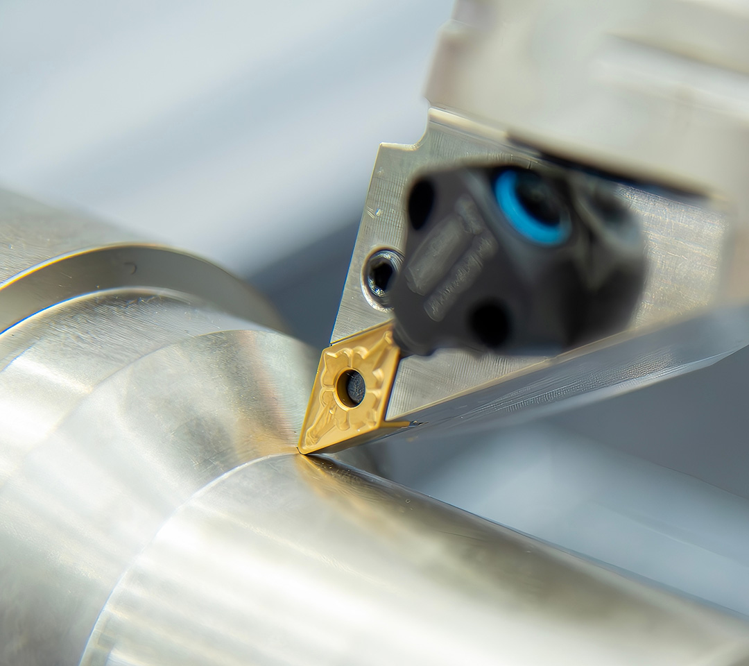

Still Troubled by Face Grooving? Get Your Complete Face Grooving Guide Now!
In grooving operations, face grooving is generally more challenging than external grooving – factors such as initial cut diameter selection, tool holder orientation, tool holder rigidity, tool interference, machining vibration, and chip evacuation all need to be comprehensively considered. To help you select the right tools faster and achieve safe and efficient face grooving, we have compiled this tool usage guide to help you reduce downtime and extend tool life!
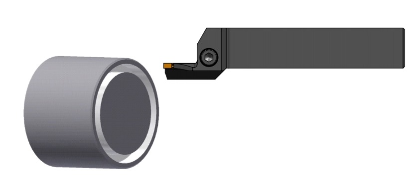
Initial Cut Diameter Range Considerations (DAXIN and DAXX)
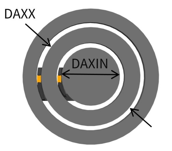
When selecting the initial cut diameter range (DAXIN and DAXX), use the largest diameter tool that matches the groove: the larger the tool diameter, the less deflection, resulting in higher rigidity and stability. This also improves chip control, as shown in the following example:
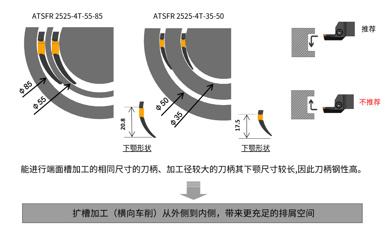
Initial Cut Interference – Key Considerations
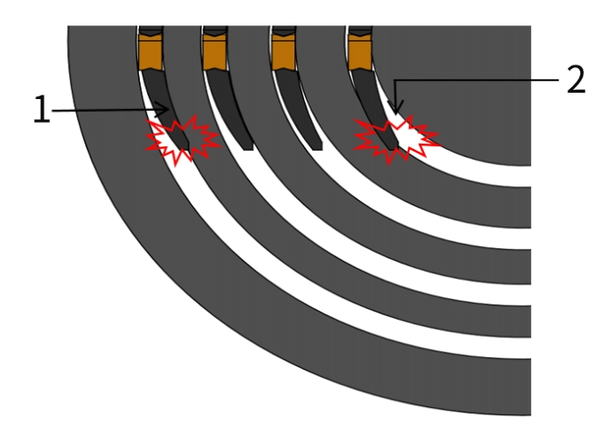
1.If the tool holder bottom support scrapes against the workpiece internal diameter during machining:
Incorrect diameter range may be selected
Tool is not parallel to the spindle axis
Check the center height
Lower the tool mounting height appropriately
2.If the tool holder bottom support scrapes against the workpiece external diameter during machining:
Incorrect diameter range may be selected
Tool is not parallel to the spindle axis
Check the center height
Raise the tool mounting height slightly
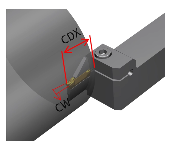
Depth of Cut (CDX)
Use the tool with the smallest possible depth of cut (CDX) to achieve higher machining stability.
Insert Width (CW)
Use the widest insert that fits the groove: the wider the cutting edge, the higher the cutting rigidity and stability.
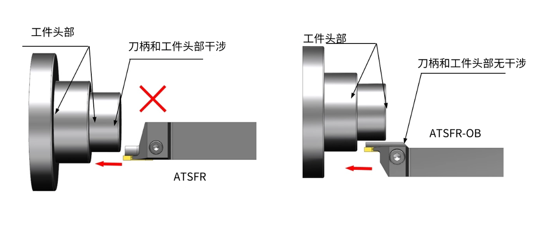
Tool Holder Orientation Selection
When performing face grooving, the presence or absence of a workpiece head determines the type of tool holder to select, as shown in the figure below:
Programming & Process Tips
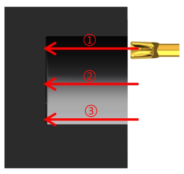
Rough Machining
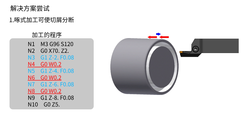
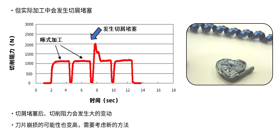
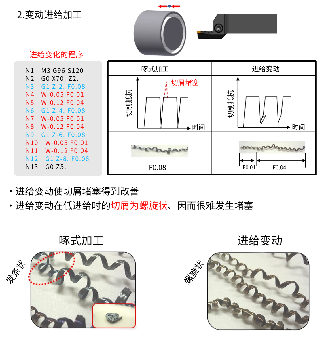
The first cut ① typically starts from the maximum diameter and works inward. This approach makes it easier to produce continuous chips and avoids chip packing in narrow grooves during machining. If shorter chips are required, programming techniques such as pecking cycles or programmed dwells can be used. The second cut ② and third cut ③ should be 0.5–0.8 times the insert width. This tool path strategy tends to produce shorter chips. At the same time, the feed can be increased by 30–50%: shorter chips are usually generated at this step.
Finish Machining
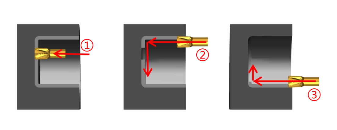
During finishing operations, achieving good chip control is always a challenge; long chips tend to form particularly when machining corner radii. In such cases, it is essential to separate the material to be removed using a 3‑cut method (see figure). The first axial cut ① is taken near the corner radius at the maximum diameter. The second cut ② starts at the maximum diameter and turns down to the inner diameter corner radius. The third cut ③ finishes the inner diameter and the corner radius.
Deep Groove Machining
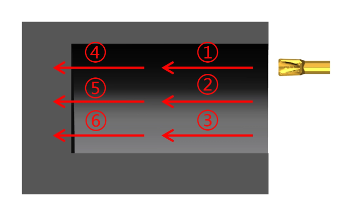
When machining grooves with a depth > 25 mm, it is recommended to complete the process in two steps as shown in the figure:
First machine 50% of the required groove depth and the full required groove width (①②③)
Then machine to the final required groove depth (④⑤⑥)
Application Case
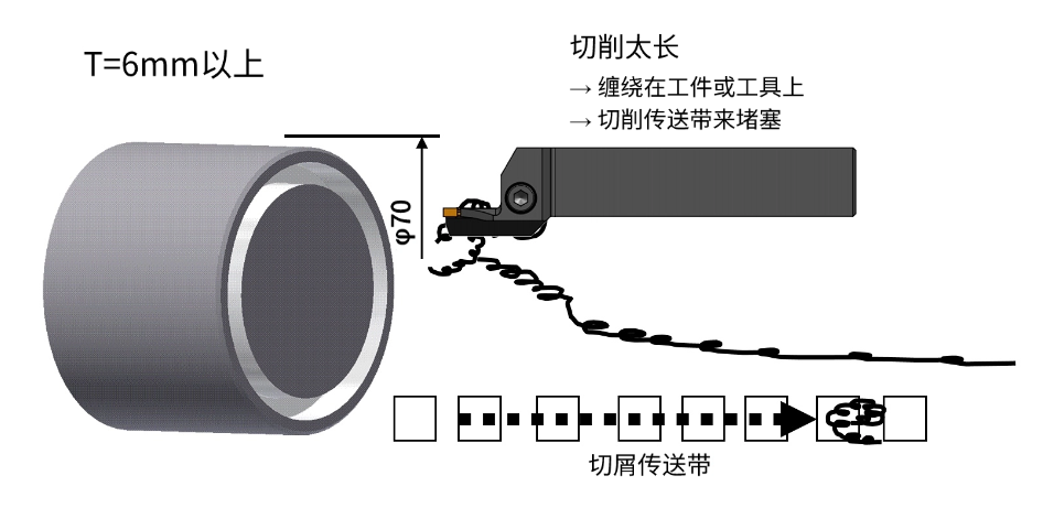
In actual face grooving operations, we encountered a chip breaking issue under the following working conditions:
Workpiece diameter: 70 mm
Material: 15CrMo
Groove depth: 8 mm
Cutting condition: Dry cutting
Cutting speed (vc): 120 m/min
Feed per revolution (f): 0.08 mm/rev